
 Submit your manual request
 Chemistry
 Construction
 Control
 Counseling
 Design and Engineering
 Electricity
 Equipment repair
 Instrumentation
 Mechanic
 oil
oil Operation, Repair and Maintenance
 Overhaul
 Period services
 Test & Commissioning
 Trade
Trade
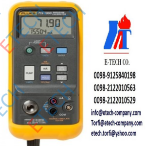

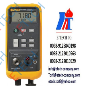
Fluke 710 Offers
Features
- Key valve testing functions – valve signature test, speed test, step test, manual test, bump/partial stroke test
- Key mA loop calibrator functions – mA source, mA simulate, mA read, mA read/loop power, and volts read
- ValveTrack™ software – enables upload to a PC for further in-depth analysis of valve measurements that are logged and recorded to memory
- Valve test procedures that deliver Good, Marginal or Bad assessment of a control valve
- Generic HART communication
- Best-in-class mA accuracy at 0.01% measurement or source value
- Compact rugged design
- Intuitive user interface with Quick-Set knob for fast setup, easy to use
- 24 V DC loop power with mA measure mode (-25 to 125%)
- Resolution of 1 μA on mA ranges and 1 mV on voltages ranges
- Built in selectable 250 Ω resistor for HART communications
- Simple two wire connection for all measurements
- Auto shutdown to conserve battery life
- Variable step and ramp time in seconds
- Offers a built-in HART modem to communicate the following HART commands:
- Read sensor PV information
- Read PV output information
- Read and write PV unit type, tag ID name, descriptor, and message
- Read and write PV ranges (upper and lower)
- Enter/exit fixed current mode
- Set zero offset
- Trim DAC zero (mA output 4 mA)
- Trim DAC gain (mA output 20 mA)
Smart Control Valve Testing is Now Easier Than Ever
The valve testing loop calibrator is designed to enable users to perform quick, easy tests on HART smart control valves. Featuring built-in test procedures and an intuitive user interface, it allows users to quickly and easily perform valve tests, while the valve test quick-check results provide at-a-glance diagnostics help you make maintenance decisions faster than ever. The valve health quick-check results let you know whether your valve is in good, marginal or in bad operating condition so you can quickly decide whether additional maintenance is necessary.
Valve Testing and HART Communication in a Precision Loop Calibrator
With the valve testing loop calibrator’s built in HART communication function, users can source a 4-20 mA signal to cause the smart control valve to move, while simultaneously interpreting the valve’s HART feedback signal to determine whether the valve is moving to the expected position. In addition to positional information, the measured pressure delivered from the valve’s internal I/P (which moves the valve) can be determined through the HART communication protocol. It has built-in test procedures that automatically increase and change the mA signal while monitoring the HART position and pressure feedback from the control valve, giving you a better overall picture of valve health at the simple push of a button.
Pre-Configured Valve Tests, At-A-Glance Answers
Valve test routines built into it include:
- Manual testing: manually change the mA signal and view the HART position and pressure variable information
- Full range ramping of the mA signal from 4 to 20 to 4 mA while recording the 0-100-0% position, or the pressures applied that move the valve from 0-100-0%
- Stepping the mA signal on the input to the valve in steps and evaluating the valves response to the mA input changes
- Speed tests to determine how fast the valve can open or close
- Bump and partial stroke tests that help test valves over a portion of their range so they can be tested in a live process
ValveTrack™ Software Enables Further Analysis and Trending
Valve tests that are logged and recorded to memory in the loop valve tester are available to upload to included ValveTrack™ analysis software.
ValveTrack™ software enables you to:
- Upload, print and plot logged valve tests taken in the field
- Compare previous uploaded tests to recent tests
- View valve test history by HART Tag ID
- Export valve test data to CSV for additional analysis in Microsoft Excel®
Saving Time, Getting Answers
In addition, it offers:
- Logging of HART data in the field – once recorded by the loop valve tester in the field, the ValveTrack™ software can upload the HART configuration of up to (20) HART devices in your plant and output data in either (.csv) or (.txt) format
- Data logged mA loop measurements and HART data can be recorded from a particular transmitter for troubleshooting and loop tuning
- The data log feature offers selectable capture with recording intervals of 1 to 60 seconds and a logging capacity of 9800 records or 99 individual sessions – each record contains the mA measurement and all four process variables
Applications
- Oil and gas
- Food and beverage
- Waste/wastewater
- Pharmaceuticals
- Process automation


Reviews
There are no reviews yet.